
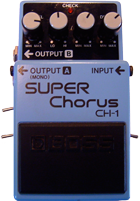

Taking apart the CH-1 is easy and its sophisticated design is actually easy to disassemble for modifications. There are four screws on the bottom, plus 1 more inside to remove. Then, tackle the pots, jacks, and footswitch. For each of these pictures, you can get a super close-up, high resolution view by double-clicking on the photo.
STEP 1: Remove the Screws Remove the 4 screws on back; pull out the battery compartment top to expose 2 more hidden screws. Remove the back plate and the black plastic insulator sitting between the backplate and the circuit board. Remove the 4 screws on back; pull out the battery compartment top to expose 2 more hidden screws. Remove the back plate and the black plastic insulator sitting between the backplate and the circuit board.Make sure to save all the screws and especially the insulator! Once you have the insulator off, you can gently pry up on the back of the circuit board - there are no screws holding the PCB in place. | |
 Here's the circuit board pulled all the way out and extended below the chassis. if you are planning on drilling out the enclosure for switches or pots, then you will definitely want to completely disconnect the circuit board from the enclosure (as shown below). If you plan on hard-wiring the mods, you can get away with it without complete disassembly. | |
STEP 2 Remove the LED PCB and Jack/Pot Nuts  Pull up on the main PCB to expose the potentiometer PCB and LED PCB. The LED PCB is held in place by a single screw. Pull up on the main PCB to expose the potentiometer PCB and LED PCB. The LED PCB is held in place by a single screw.Once you get this screw out, you can pull out the PCB and then pull apart and separate the main PCB and potentiometer wiring harness from the unit. Next, remove the nuts from the input and output jacks. Pull off the plastic knobs and remove the nuts for the potentiometers. | |
STEP 3: Disconnect the footswitch  De-solder the purple and black wires going to the footswitch. Once you have them off, press the two tabs on either side of the switch to free it and push out down toward the battery compartment. De-solder the purple and black wires going to the footswitch. Once you have them off, press the two tabs on either side of the switch to free it and push out down toward the battery compartment.Once it comes out you can thread the battery connecter harness back out through the switch hole. This will completely free the circuit board, pots and jacks. | |
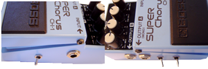
STEP 4: Drill out the Mod Holes  This is where you have some decisions to make. The Input Drive and Output Gain mods could be done with potentiometers, so you have complete control. The LFO Mod is done solely with a switch. I decided that because of the limited space in the enclosure to make my mods switchable with micro-toggle switches. I chose the areas on the left and right just behind the input jacks. This gave plenty of room for the new wiring harness. It's up to you exactly how you want to do this step - read the mods first and then decide, or follow along with my suggestions. This is where you have some decisions to make. The Input Drive and Output Gain mods could be done with potentiometers, so you have complete control. The LFO Mod is done solely with a switch. I decided that because of the limited space in the enclosure to make my mods switchable with micro-toggle switches. I chose the areas on the left and right just behind the input jacks. This gave plenty of room for the new wiring harness. It's up to you exactly how you want to do this step - read the mods first and then decide, or follow along with my suggestions. |


How can i open the footswitch?
ReplyDeletethanks
Saya punya sh-1 super chorus ada kendala lampu LED tidak menyala ....bgmn solusinya
ReplyDeleteRalat maksud nya super chorus
ReplyDelete