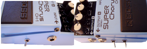
CH-1 Superchorus Mods

My chorus always seemed to mush out the sound and get lost in the mix. Have you ever wanted a Chorus with a LOUDER output and more drive? Try these mods!

  • Input Drive Control
  • Output Gain Control
  • LFO Mod for Triangle to Sawtooth Morph + Extended Rate; this Mod can sound like a rotary speaker and extends the maximum Rate as well.

These mods are of my own design and I have not seen them anywhere else. The schematics are well documented and available all over the internet. BOSS, SUPERChorus, and CH-1 ARE TRADEMARKS OF THE ROLAND CORPORATION AND ARE USED FOR REFERENCE ONLY. THIS SITE IS NOT AFFILIATED WITH THE ROLAND CORPORATION IN ANY WAY.

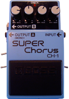
Input Drive Mod


The Input Drive mod changes the gain of the input filter. The second stage of the circuit is the input filter which is a lowpass filter prepping the signal for the analog bucket-brigade device. The gain of the filter is set by R3 and R5 which are both 47k giving a gain of 1. R3 and R5 will also affect the corner frequency of the filter. C31 just below R3 sets this value. Theoretically, changing R3 would require changing C31 also but I found that this was not really necessary. The mod works like this:

To increase the input drive going to the chorused half of the output, DECREASE R3 or INCREASE R5. It's easiest to decrease R3. You could switch in another 47k resistor across it. I wanted more gain than that so I used a 10k resistor and made it switchable with the 47k one in case I changed my mind later. You could also use a micro-trimmer pot on the inside of the enclosure to adjust manually.


STEP 1: Locate R3 and remove it
R3 is located near the ribbon connector side of the PCB just below the SIP op-amp. Flip the PCB over and de-solder R3 and remove it from the PCB leaving clean through-holes for wiring the mod.


STEP 2: Add Mod wires in place of R3
I cut several sets of mod wires about 6" long for all the mods. Strip, tin, and insert one wire into each hole left by R3. These wires will travel out to the switch where the other resistors will be located. Its much easier to wire the resistors to the switch than to the cramped PCB.

STEP 3: Wire the Switch
The switch is wired with the original 47k resistor on one side, and the new 10k resistor on the other. They are soldered together at one end. Solder this end with a heat shrink tubing to one of the R3 mod wires, and solder the center pin of the switch to the other R3 mod wire.


STEP 4: Wire and Test Fit
Wire up the switch (don't forget the heat shrink tubing where necessary. Then test fit it in the enclosure. You can see that here in the white circle. I mounted the Input Drive Mod switch on the same side as the input jack.


Home | Schematics | Disassembly | Input Drive | Output Gain | LFO Mod

1 comment:

  1. I'm wondering if you have a parts list for these mods?

    Are those switches On/On SPDT?

    ReplyDelete