
 The LFO Mod is certainly the most interesting. This mod allows the normal triangle wave LFO to morph into a sawtooth wave as you turn up the Rate knob. At low values for Rate, there is no effect. As you increase the rate past 12'00 the triangle slowly morphs with a sawtooth wave. At the very top of the Rate control, the waveform is pure sawtooth. The LFO Mod is certainly the most interesting. This mod allows the normal triangle wave LFO to morph into a sawtooth wave as you turn up the Rate knob. At low values for Rate, there is no effect. As you increase the rate past 12'00 the triangle slowly morphs with a sawtooth wave. At the very top of the Rate control, the waveform is pure sawtooth.This device uses a 7-color blinking LED device available from Radio Shack (276-016). This device has 3 pins: Mode, Vdd, Gnd and the trick is to cut off the middle leg, Vdd. Then, feed the triangle wave into the Mode-Gnd pair of pins. When the rate gets high enough, the IC built into the LED powers up and begins to light the Red LED (you can see it light up). As the rate increases, the LED gets brighter and the triangle waveform becomes more and more sawtooth-ish in nature. At the top of the range the LFO is pure sawtooth and the LED is blinking brightest. My guess is there is a transistor comparator type of circuit inside that engages more diodes (including the drops in the base-emitters of the transistors), ramping out the triangle wave. The sawtooth can be rising edge or falling edge by swapping the orientation of the LED device (Mode-Gnd). To use this, switch it in parallel with the 15k resistor (do not switch out the resistor as the LFO will become almost insignificant in amplitude). | |
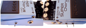
STEP 1: Locate R56 and Replace it with a bigger one  R46 is located near the ribbon connector side of the PCB near the bottom edge. Flip the PCB over and de-solder R46 and REPLACE it with a larger version - this is purely a geometry issue. You need to wire the LED device in PARALLEL with it and you need to do this from the component side, not the other. If you can wrestle with the existing one, fine. I changed mine out for a 1/4W Radio Shack version. R46 is located near the ribbon connector side of the PCB near the bottom edge. Flip the PCB over and de-solder R46 and REPLACE it with a larger version - this is purely a geometry issue. You need to wire the LED device in PARALLEL with it and you need to do this from the component side, not the other. If you can wrestle with the existing one, fine. I changed mine out for a 1/4W Radio Shack version. | |
STEP 2: Add Mod wires across R46  Here you can see the new R46 in place with legs bent out to expose them and give some room to solder the jumper mod wires across. Here you can see the new R46 in place with legs bent out to expose them and give some room to solder the jumper mod wires across.Here you can see all 3 mod wires in place. | |
STEP 3: Wire the Switch  The switch is a SPST type with an open circuit (N/C) on one side. The LED device is connected to the other side. The center leg of the LED has been removed. With a little bit of cerebral work, you can figure out a way to switch it to operate either way as a rising edge or falling edge sawtooth waveform (hint, use a DPDT switch). The switch is a SPST type with an open circuit (N/C) on one side. The LED device is connected to the other side. The center leg of the LED has been removed. With a little bit of cerebral work, you can figure out a way to switch it to operate either way as a rising edge or falling edge sawtooth waveform (hint, use a DPDT switch). | |
STEP 4: Wire and Test Fit  Wire up the switch (don't forget the heat shrink tubing where necessary. Then test fit it in the enclosure. You can see that here in the white circle. I mounted the LFO Mod switch on the same side as the output jack. Wire up the switch (don't forget the heat shrink tubing where necessary. Then test fit it in the enclosure. You can see that here in the white circle. I mounted the LFO Mod switch on the same side as the output jack. |
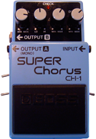
CH-1 Superchorus Mods
My chorus always seemed to mush out the sound and get lost in the mix. Have you ever wanted a Chorus with a LOUDER output and more drive? Try these mods!
|
|
These mods are of my own design and I have not seen them anywhere else. The schematics are well documented and available all over the internet. BOSS, SUPERChorus, and CH-1 ARE TRADEMARKS OF THE ROLAND CORPORATION AND ARE USED FOR REFERENCE ONLY. THIS SITE IS NOT AFFILIATED WITH THE ROLAND CORPORATION IN ANY WAY.

LFO Sawtooth Mod
Subscribe to:
Post Comments (Atom)


The other 2 mods are simple enough for me. But this one, I'm not sure of.
ReplyDeleteRepalce R56 with a bigger one and replace R46 with a larger one? Bigger resistors? What size?
What is the optional 1/4 watt thing from Radio Shack...a pcb?
Thanks,
Mike
mikespi8@sbcglobal.net
There's an led with 3 legs?
ReplyDeleteAm I the only one interested in the CH-1 LFO Sawtooth mod?
ReplyDeleteCan I see a picture of the finished, wired switch? I tried this, can't hear a difference. I really want this to work.
Thanks,
Mike
modestmike@att.net
I've tried the lfo mod but it doesn't work!
DeleteThanks
So, it does make a difference...the order in which the wires hook to the pcb.
ReplyDeleteSo I finally got it to work, now I can stop wondering about it.
I see no need for it. Y ou have to have the rate very fast in order for this effect to work, so what can you use the effect for? Maybe someone could tell me when to use a fast rate in a song, to get a certain effect...?
Looks like you figured out your own questions: the larger resister means physically larger so you have leads to solder to; the wires have to be on the top. I used to work for a well known synth company and got turned on to using sawtooth and other LFOs in chorusing modules. The fast rate and sawtooth to me starts sounding like a uni-vibe a bit.
ReplyDeleteBTW, a bunch of images were lost when a friend took over one of my websites, so I will be patching up this site and the others soon.
Hey guys, how about the c18 (47pF) mod? I did using variables caps, higher, lower values and no cap. Its amazing.....
ReplyDelete